Tools & Inspiration For Craftsmen
Shop Now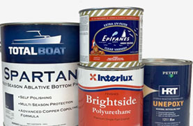
Top Products
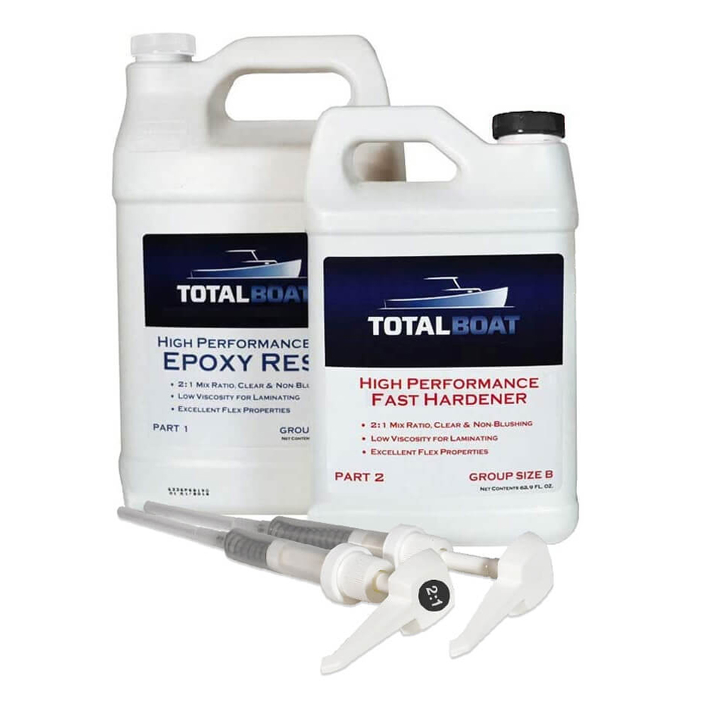
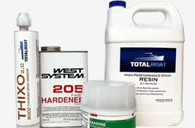
TotalBoat
TotalBoat High Performance Epoxy Kits
Starting at $39.99
rating 4.8 out of 5 stars
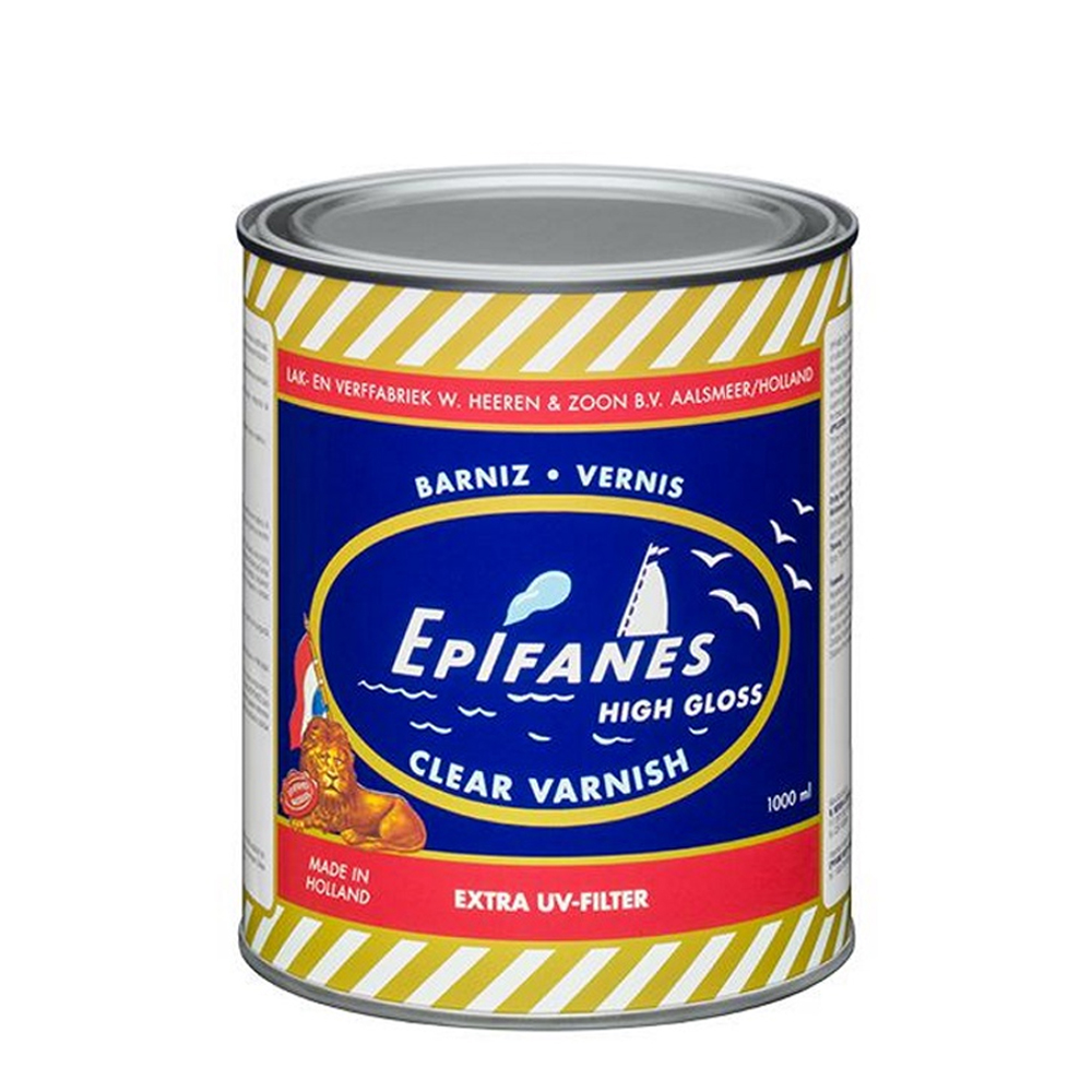
Epifanes
Epifanes Clear High-Gloss Marine Varnish
Starting at $21.73
rating 4.8 out of 5 stars
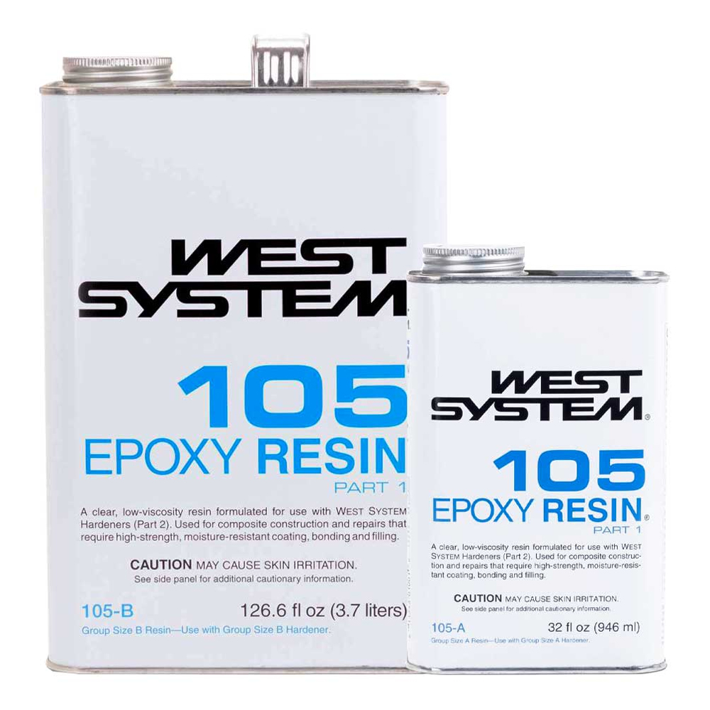
WEST System
WEST System 105 Epoxy Resin
Starting at $49.97
rating 4.8 out of 5 stars
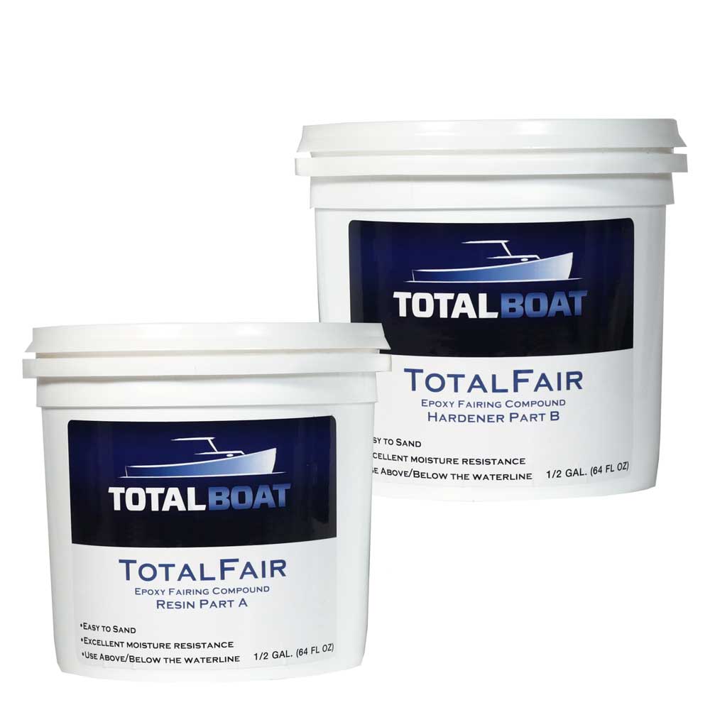
TotalBoat
TotalBoat TotalFair Epoxy Fairing Compound
Starting at $44.99
rating 4.7 out of 5 stars
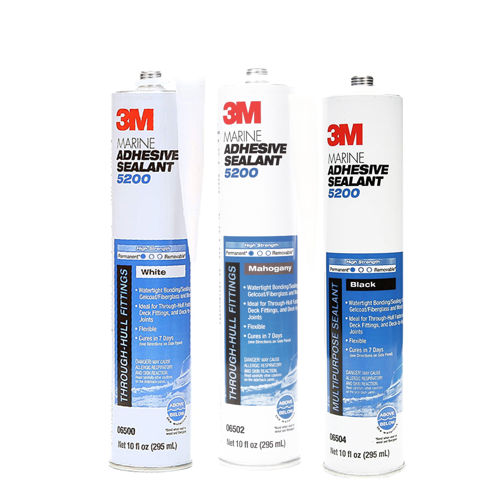
3M
3M 5200 Marine Adhesive Sealant
Starting at $14.97
rating 4.8 out of 5 stars
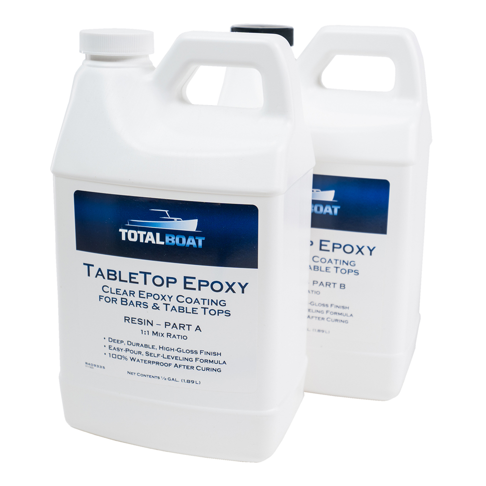
TotalBoat
TotalBoat TableTop Epoxy
Starting at $52.99
rating 4.8 out of 5 stars
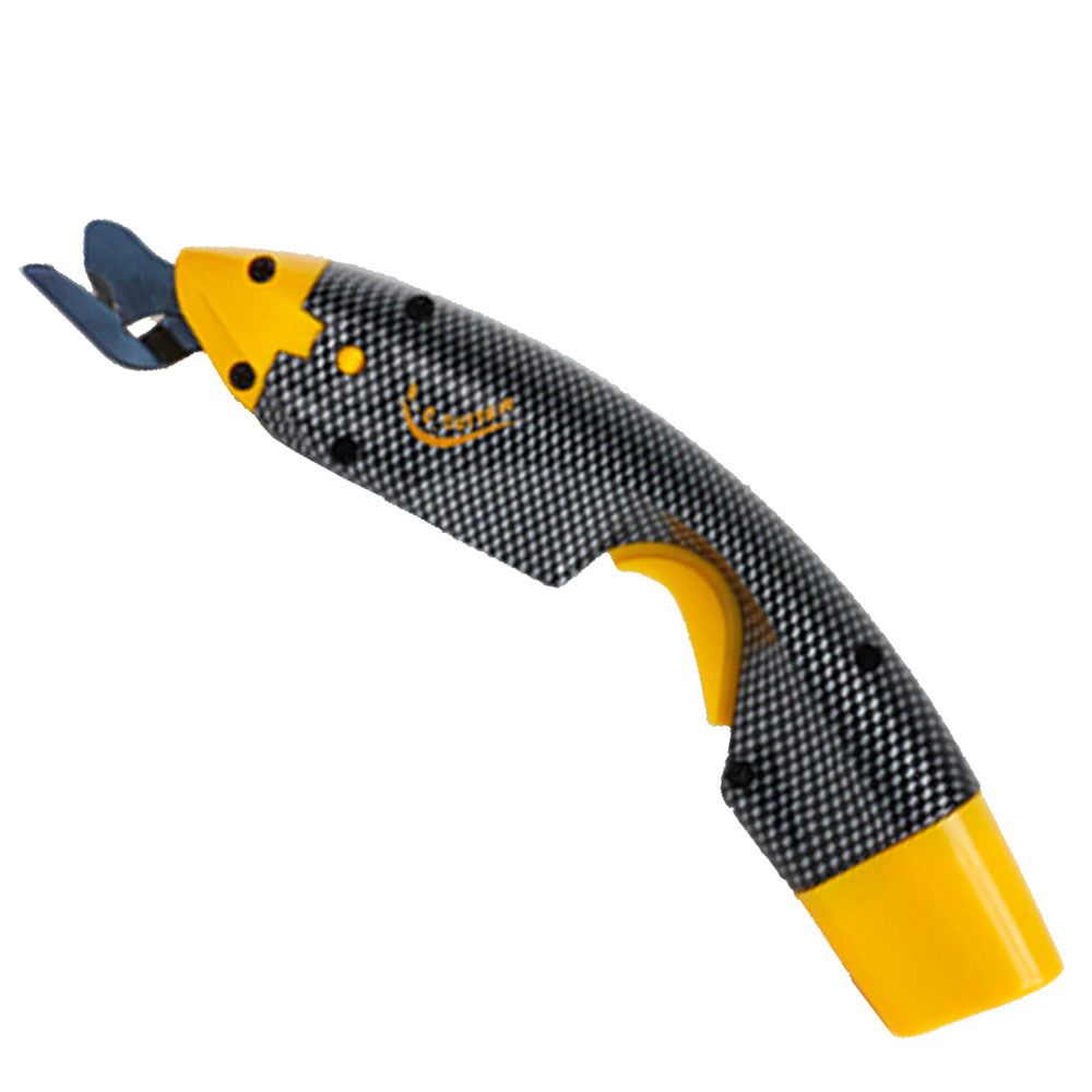
EC Cutter
EC Cutter Electric Cordless Scissors
Starting at $
rating 4.5 out of 5 stars
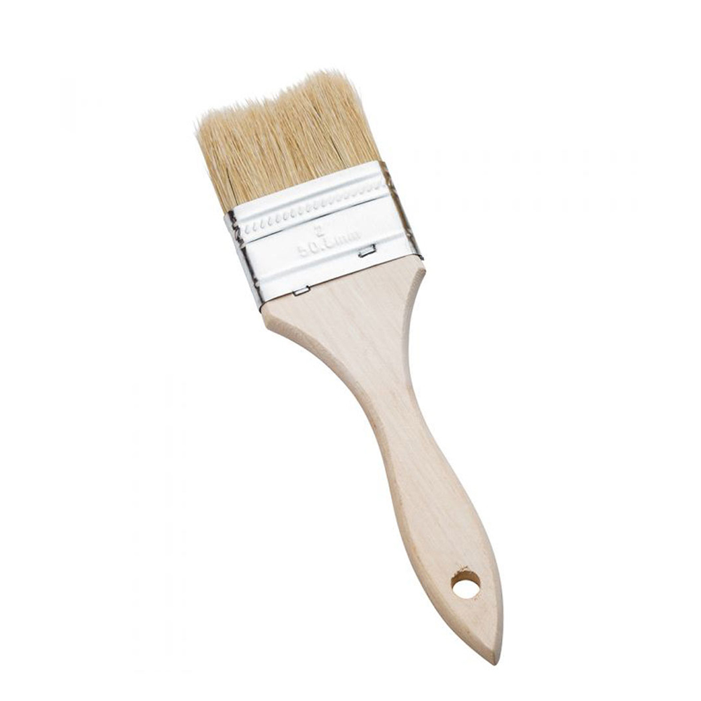
Jamestown Distributors
Chip Brushes
Starting at $5.64
rating 4.7 out of 5 stars
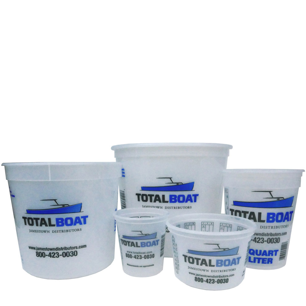
Jamestown Distributors
Plastic Paint Pails
Starting at $3.75
rating 4.7 out of 5 stars
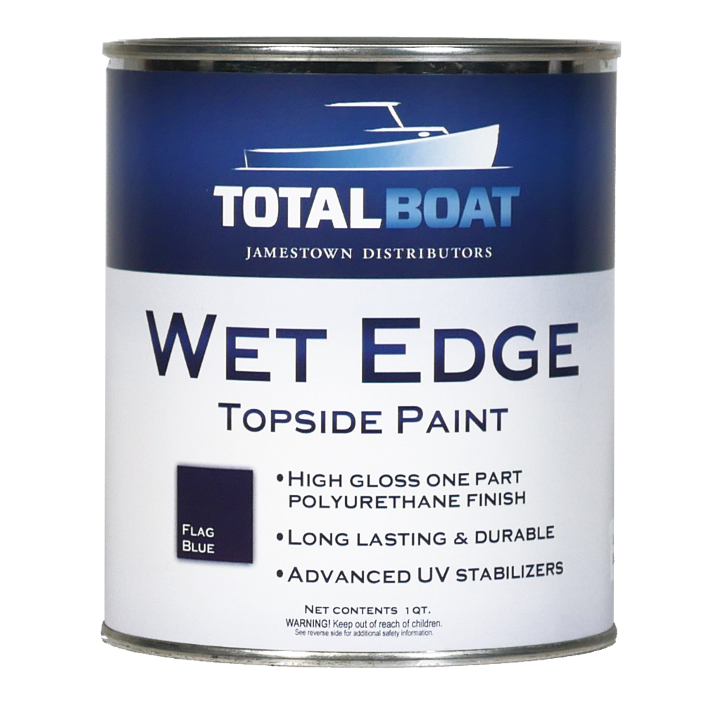
TotalBoat
TotalBoat Wet Edge Topside Paint
Starting at $31.99
rating 4.6 out of 5 stars


Totalboat
Explore the most comprehensive lineup of marine maintenance & repair solutions available. DIY makers & woodworkers prefer TotalBoat products for their ease of use and marine-grade durability
SHOP NOWPopular Brands


About Us
Our mission is to provide Tools and Inspiration for Craftsmen . We've been supplying building & maintenance products to boaters, builders & DIY makers since 1977. We love to help people build stuff!
Learn MoreFree Shipping!
Shop Now